
Recovery of Acetic Acid
From Aqueous Waste Streams
- Maximum removal of acetic acid from water
- Recovery of other organic side products
- Minimum content of organics in waste water
- Minimum energy consumption
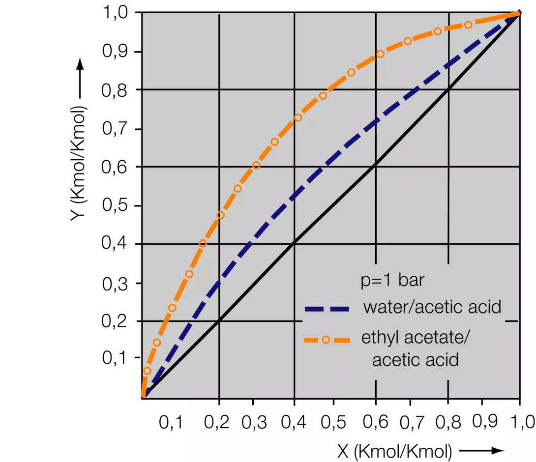
Acetic acid is the most widely used aliphatic carbonic acid. Apart from its use as a reaction partner, e.g. during the production of acetic-acid esters, it is frequently also employed as a solvent, for instance, during the production of cellulose acetate or during the manufacture of pharmaceutical products. In most cases its recovery is of great economic significance. Separation of the acetic acid and water mixture by rectification is economically disadvantagous since this mixture has a very small thermal separation factor. This would require a high rectification column with a huge number of separation stages which would have to be operated with a high reflux ratio. This would necessarily involve high energy and high operating costs. In practice, therefore, azeotropic rectification has asserted itself and operates either with or without the extraction stage, depending on the respective acetic-acid concentration. The addition of an auxiliary substance means that the volatility of the water is increased, which in turn means that separation can be achieved with lower energy consumption. In the case of acetic-acid concentrations of below 40 wt%, the acetic acid is initially extracted from the aqueous solution with a suitable extraction agent, before pure recovery occurs during the rectification of the azeotropic mixture.
The recovery method using extraction must be taken into consideration, irrespective of the concentration, if supplementary impurities in the initial mixture, like salts, would be likely to cause problems during direct recovery by distillation. This technical-information leaflet deals with the recovery of acetic acid by means of liquid-liquid extraction and downstream azeotropic rectification.
SELECTION OF THE EXTRACTION AGENT
Normally, more low boiling extraction agents are used. Characteristics like solubility in water, absorption capacity, distribution coefficient, price, availability and composition of the azeotrope, and requirements in terms of environmental and health protection must be taken into account for the purpose of this selection.
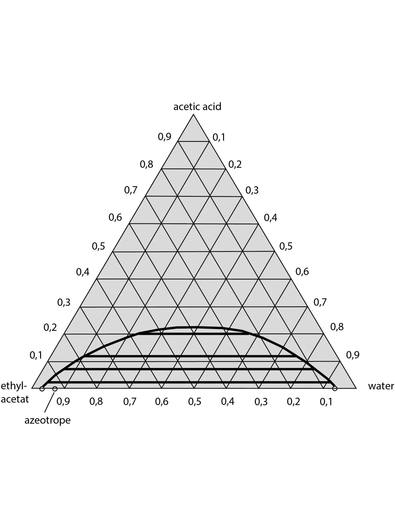
Table 1 shows a selection of extraction agents suitable for the recovery of acetic acid, with details on the average distribution coefficient between the organic and aqueous phase, density of the extraction agent at 20°C; enthalpy of vaporisation and boiling point temperature of the extraction agent; and the proportion of water and temperature of the binary azeotrope between extraction agent and water. The average distribution coefficients do not differ essentially from one another. As a result, all the extraction agents listed here must be regarded as practically equivalent with regard to the extraction. The economic viability of the overall rocess greatly depends on the energy requirements of the solvent rectification, which in turn depends on the reflux ratio and thus on the performance of condenser and evaporator. The difference in boiling emperatures between the pure acetic acid (118°C) and the azeotropic point provides clue on the size of the reflux ratio. According to this, the reflux ratio in the case of all the extraction agents listed here ought to be in the same order of magnitude. The energy consumption, however, also depends on the vaporisation enthalpy of the azeotropic mixture, which in turn is determined by the proportion of water in the azeotrope. Thus the energy consumption in the case of the use of EtAc or MTBE as extraction agents ought to be the lowest. It can be shown that these observations only apply up to certain feed concentrations of acetic acid, which, for example, amount to approx. 15wt% in the case of ethyl acetate and MTBE. If the feed concentrations are higher, then the quantity of extraction agent must be increased in accordance with the balance and vapour-liquid equilibrium, which consequently causes an increase in the operating costs. A more favourable alternative in terms of energy is the QVF® method described below. By means of appropriate process principle, economic working of the entire procedure can be achieved, even with high inflow concentrations of acetic acid. It can be gathered from the liquid-liquid equilibrium for the two preferred ternary systems (see figs. 3 and 4) that if ethyl acetate is used, there is considerable reciprocal solubility with water.
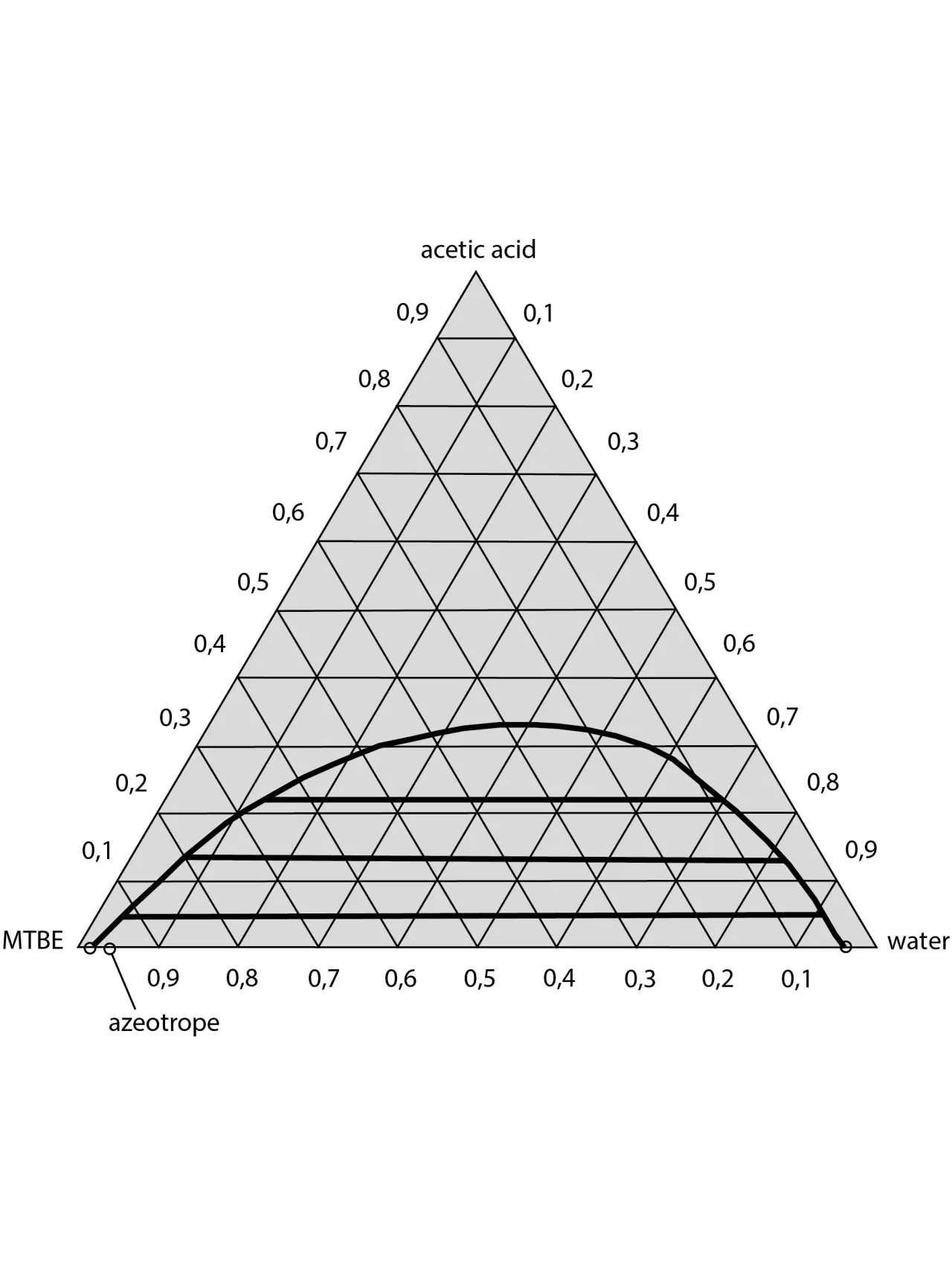
The space in the immiscibility gap is relatively small, so that feed concentration of 30 wt% should not be exceeded for safe extraction work. On the other hand, the immiscibility gap in the case of the MTBE / acetic-acid / water system is more pronounced, and the reciprocal solubility lower. Feed mixtures with acetic-acid concentrations of up to around 40 wt% can, therefore, be reprocessed without problem using MTBE as the extraction agent.
| Name | Average distribution coefficient | Density | Enthalpy of vaporisation | Boiling Point | Azeotrope |
| kg/kg | kg/m³ | kJ/kg | °C | Water T Wt % °C | |
| Ethyl acetate C4H8O2 | 0,84 | 900 | 395 | 76,7 | 8,47 70,4 |
| Isopropyl acetate, C5H10O2 | 0,55 | 877 | 361 | 88,6 | 10,50 76,5 |
| n-Propyl acetate, C5H10O2 | 0,50 | 891 | 336 | 101,6 | 13,20 82,2 |
| Methylpropyl ketone, 2-pentanon, C5H10O | 0,97 | 810 | 384 | 102,3 | 19,50 83,3 |
| Methylisobutylketon, 4 Methyl- 2-Pentanon C6H12O | 0,50 | 810 | 488 | 115,9 | 24,30 87,9 |
| Methyl-tert.-butyl ether, C5H12O | 0,75 | 740 | 322 | 55 | 4 52,6 |
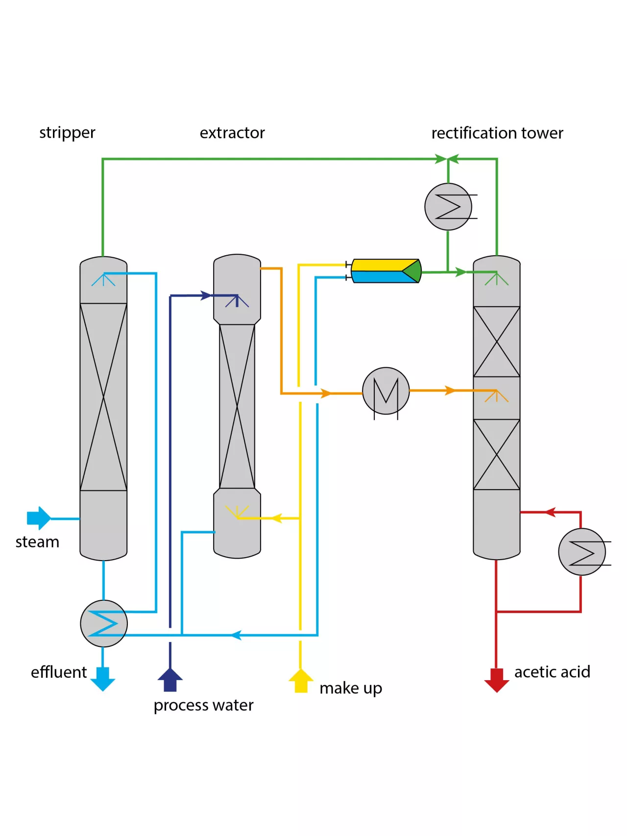
EXTRACTION PROCESS
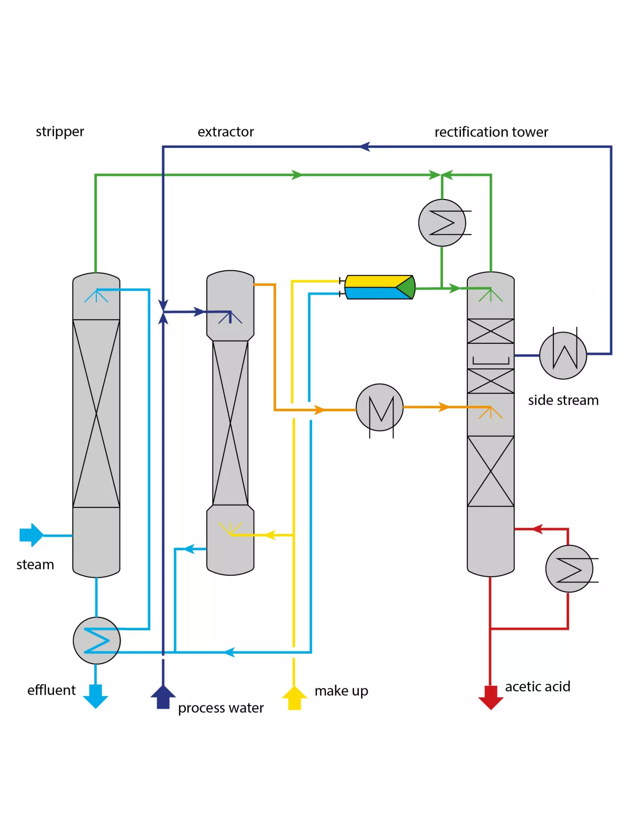
The figure shows the flow chart of a conventional extraction plant for the recovery of acetic acid. It consists of the extraction tower, the rectification tower for the recovery of the extraction agent, and the water-stripping tower. As a rule, the feed mixture has a greater density than the solvent, and is fed in at the top end of the extraction tower. Inside the tower it streams towards the bottom and in the process gives off acetic acid to the extraction agent. Depending on the effort, residual concentrations of 0.1-0.5 wt% can be achieved. Since the aqueous phase is simultaneously saturated with the extraction agent in the extraction tower, it is recovered in a downstream stripping tower. It can in this respect be performed with live steam. The extraction agent accumulate at the top end of the rectification tower and the acetic acid at the bottom of the tower resulting in acetic-acid concentrations of practically 100 wt%. If there is a risk of any higher-boiling components also passing into the organic phase during extraction, then it is recommended that the acetic acid should be discharged in vapour form. The following figure shows the flow chart of the QVF® process. Here, similar to the conventional method, acetic acid is also extracted during the extraction stage from the process water with the aid of a suitable extraction agent (MTBE in most cases). The extraction tower, however, is operated in such a way that a high a concentration as possible of acetic acid is achieved during the extraction-sequence phase with simultaneous fulfilment of the required raffinate purity. During this operation the extracted phase contains a high proportion of acetic acid and, consequently, also water. In the downstream rectification stage, separation of the extracted phase now occurs in an azeotropic mixture consisting of extraction agent and water, and in acetic acid of the required concentration. The excess water present in the extracted phase is distilled as a liquid side-stream in the rectifying section of the rectification tower. A particularly favourable choice of the draw off point and reflux ratio can result in a composition in the side stream, which approximately corresponds to that of the process water. After cooling to the operating temperature of the extract phase, the side stream is guided back into the extraction tower. The position of the feeding point depends on the concentration of the acetic acid in the side stream.
The costs of the whole process are determined by the costs for the separation of the extraction agent from the acetic acid. Meticulous care is therefore necessary both in terms of the design and layout of the control system of this process stage. In the case of the classical process with ethyl acetate or MTBE as extraction agents, separation can occur without problems. Nevertheless it should be taken into account that in the tower a ratio of ethyl acetate to water is set at which the separating factor relative to acetic acid is at its greatest. This is potentially very simple if the inlet concentration of acetic acid in the process water is below 15 wt%. In the case of the QVF® process the rectification step is also unproblematic. Nevertheless, the control system of the tower is more expensive by comparison with the conventional method, i.e. a certain concentration profile must be adjusted in the tower with a distinctive concentration maximum for water.
In addition the flow rate of the side stream must be controlled. The automatic control-technology concept developed by de Dietrich Process Systems for this purpose has already proven outstandingly good in practical applications.
OPERATING COSTS
Greater expenditure in the case of the QVF® process is justified by the up to 40% lower energy equirement by comparison with the classical process. This saving in energy results from the low extraction agent main stream. As a result, high acetic-acid concentrations develop in the extract, so that the proportion of water in the extract is also higher than in the case of the classical process. However, this excess water is drawn off as a liquid side from the rectification tower. As a result, it is possible to achieve azeotropic composition in the distillate, and then only the quantity of water contained therein has to be condensed in the top end of the tower. It is not possible to make any generally applicable statements on the operating costs of acetic-acid recovery, since these depend on the inflow concentration of the acetic acid, run-off concentrations of the products, type of extraction agent, choice of method variations, and heat recovery etc. For the purpose of the assessment two (sets of) reference values are given below for each method. The figures apply to the use of MTBE, and assume that 99 wt% liquid boiling acetic acid is being distilled at the bottom of the rectification (tower).
The duty of the evaporator for the classical process amounts to the following:
- approx. 280 kW per 100 kg/h of acetic acid with an acetic-acid concentration of 10 wt%, and
- approx. 260 kW per 100 kg/h of acetic acid with an acetic-acid concentration of 35 wt%.
The following values have been calculated for the QVF® process:
- approx. 260 kW per 100 kg/h of acetic acid with an
- acetic-acid concentration of 10 wt%, and
- approx. 180 kW per 100 kg/h of acetic acid with an
- acetic-acid concentration of 35 wt%.
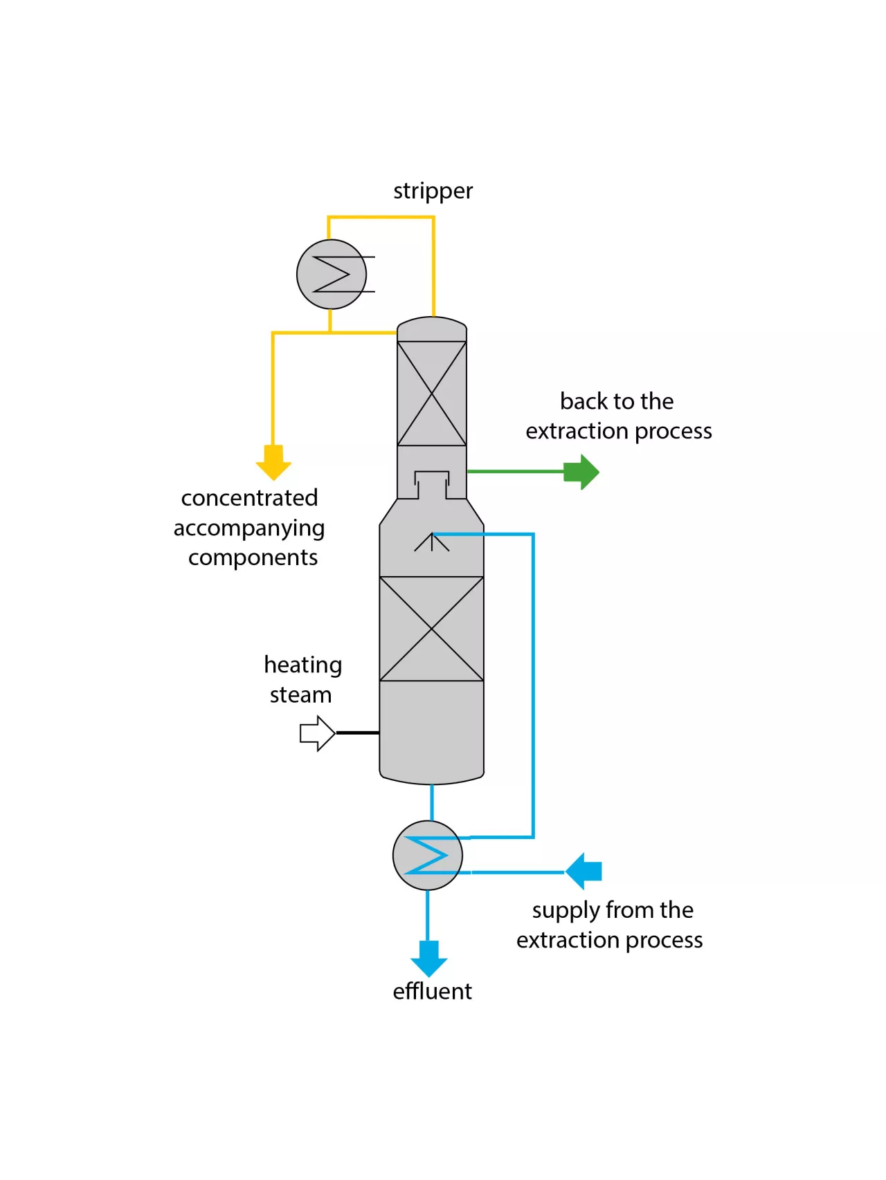
DRAWING OFF ACCOMPANYING COMPONENTS
In many cases the process water contains low boiling components like ethanol or acetone, which must be removed along with the acetic acid. Using MTBE as an extraction agent, this can be performed as follows. During the steady-state operation the low boiling components pass the extraction tower without being extracted and reach a downstream stripper, which is equipped with a rectifying section (see figure).
In the stripper section of the tower the water is cleared of the extraction agent and accompanying components. On the other hand, the rectifying section of the tower is used to separate MTBE from the accompanying components. However, during the separation of components, which have a small boiling-temperature difference to MTBE (e.g. acetone), MTBE losses can be expected. In this case it is possible to resort to another variation in the process. For this purpose a water stripper without rectifying section is used. Nevertheless, the stripper is operated in such a way that the accompanying components are driven to the bottom of the tower and the extraction agent driven to the top of the tower. In this case, however, it is necessary for the loaded aqueous phase to be purified, for example, by a biological treatment.
You have questions?
Documents to download
Request a download
In order to process your brochure request efficiently, we kindly ask you to provide the required information through our form.